Features:
- Broadband
- Small Size
- Low Insertion Loss
 +86-28-6115-4929
  sales@qualwave.com


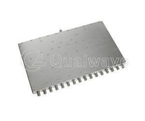
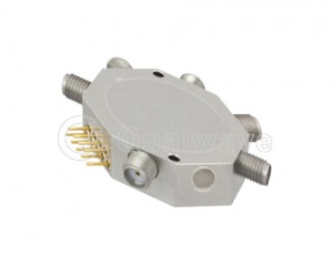
The structure of a 11-way high power divider/combiner is generally composed of input end, output end, reflection end, resonant cavity, and electromagnetic components. The basic working principle of a power divider is to divide an input signal into two or more output signals, with each output signal having equal power. The reflector reflects the input signal into a resonant cavity, which divides the input signal into two or more output signals, each with equal power.
The 11 channel power divider/combiner can meet the specified requirements for separating or combining data signals between 11 inputs or outputs.
The key indicators of a 11-way resistor power divider/combiner include impedance matching, insertion loss, isolation degree, etc.
1. Impedance matching: By distributing parameter components (microstrip lines), the problem of impedance mismatch during power transmission is solved, so that the input and output impedance values of the power divider/combiner should be as close as possible to reduce signal distortion.
2. Low insertion loss: By screening the materials of the power divider, optimizing the manufacturing process, and reducing the inherent loss of the power divider; By selecting reasonable network structure and circuit parameters, the power division loss of the power divider can be reduced. Thus achieving uniform power distribution and minimum common loss.
3. High isolation: By increasing isolation resistance, the reflected signals between output ports are absorbed, and the signal suppression between output ports is increased, resulting in high isolation.
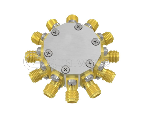
1. A 11-way microwave power divider/combiner can be used to transmit a signal to multiple antennas or receivers, or to divide a signal into several equal signals.
2. A 11-way millimeter wave power divider/combiner can be used in solid-state transmitters, directly determining the efficiency, amplitude frequency characteristics, and other performance of solid-state transmitters.
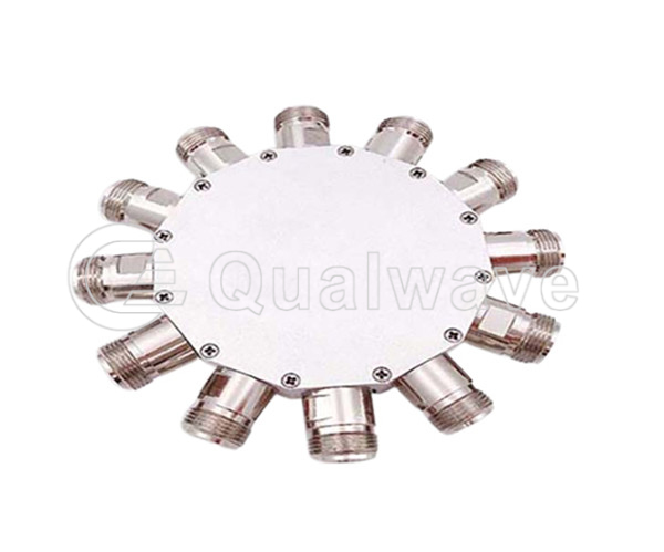
Qualwave inc. provides 11-way broadband power divider/combiner in the frequency range of DC to 1GHz, with a power of up to 2W.

Part Number |
RF Frequency(GHz, Min.)  |
RF Frequency(GHz, Max.) |
Power as Divider(W) |
Power as Combiner(W) |
Insertion Loss(dB, Max.) |
Isolation(dB, Min.) |
Amplitude Balance(±dB,Max.) |
Phase Balance(±°,Max.) |
VSWR(Max.) |
Connectors |
Lead Time(Weeks) |
|---|---|---|---|---|---|---|---|---|---|---|---|
| QPD11-0-3000-2 | DC | 1 | 2 | - | 20.0±1.5 | 20 | ±0.5 | - | 1.3 | N | 2~3 |