Features:
- Broadband
- Small Size
- Low Insertion Loss
 +86-28-6115-4929
  sales@qualwave.com


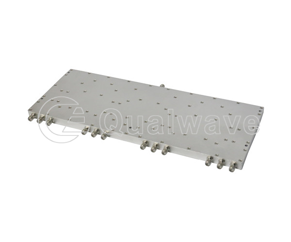
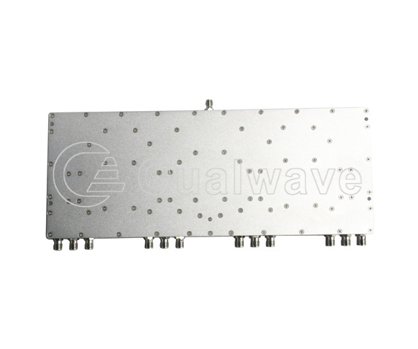
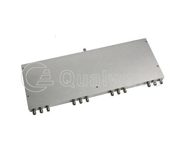
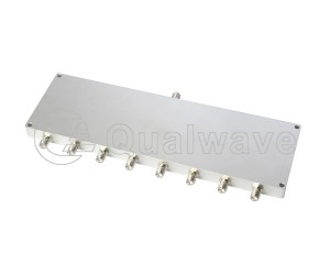
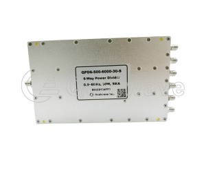
A power divider is a key device used in wireless communication systems to allocate input RF power to different output ports. A 12 channel power divider/combiner can meet the specified requirements for separating or combining data signals between 12 inputs or outputs.
We provide 12-way microwave power divider/combiner, 12-way millimeter wave power divider/combiner, 12-way resistor power divider/combiner.
1. Small size: By reducing the distance between microstrip lines, the volume of the centimeter board is reduced, thereby reducing the volume and size of the power divider/combiner.
2. Low insertion loss: The loss of the 12-way microstrip power divider/combiner refers to the loss of signal power caused during the power divider process. By selecting low loss production materials, optimizing design and production processes, using supplementary networks or circuits to compensate and correct losses, reducing insertion losses, and ensuring system stability.
3. High consistency in phase and width: using excellent substrate materials and gold plating process, the product indicators and performance consistency are significantly improved, and the work is stable and reliable.
1. Phased array field: Allocate to different antenna components according to the set phase and amplitude, thereby achieving functions such as beam forming, beam scanning, beam transmission and reception.
2. Solid state power synthesis field: The application in the field of solid state power synthesis mainly involves the synthesis, allocation, and control of RF signals. Through reasonable power allocation and beamforming, higher output power, signal-to-noise ratio, and system performance can be achieved.
3. Multi channel relay communication field: The application of power splitters/combiners in the field of multi channel relay communication mainly involves parallel allocation and transmission of signals. By providing multiple communication paths and interfaces, efficient data transmission and improvement of communication quality are achieved.
Qualwave inc. provides 12-Way high power power divider/combiner, with a frequency range of DC~40GHz, power up to 100W, maximum insertion loss of 24.5dB, minimum isolation of 15dB, maximum amplitude balance of ±2dB, maximum phase balance of ±20°.

Part Number |
RF Frequency(GHz, Min.)  |
RF Frequency(GHz, Max.) |
Power as Divider(W) |
Power as Combiner(W) |
Insertion Loss(dB, Max.) |
Isolation(dB, Min.) |
Amplitude Balance(±dB,Max.) |
Phase Balance(±°,Max.) |
VSWR(Max.) |
Connectors |
Lead Time(Weeks) |
|---|---|---|---|---|---|---|---|---|---|---|---|
| QPD12-0-4000-2-N | DC | 4 | 2 | - | 23.6 | 20 | ±2 | - | 1.5 | N | 2~3 |
| QPD12-0-5000-2-S | DC | 5 | 2 | - | 24.5 | 20 | ±0.9 | ±9 | 1.3 | SMA | 2~3 |
| QPD12-200-2000-1-S | 0.2 | 2 | 1 | 1 | 5.2 | 16 | ±1.5 | ±20 | 1.7 | SMA | 2~3 |
| QPD12-240-30-S | 0.24 | - | 30 | 2 | 0.8 | 20 | 0.5 | ±4 | 1.3 | SMA | 2~3 |
| QPD12-300-18000-30-S | 0.3 | 18 | 30 | 5 | 10 | 18 | ±0.8 | ±12 | 1.6 | SMA | 2~3 |
| QPD12-400-6000-10-S | 0.4 | 6 | 10 | 1 | 5.8 | 18 | ±1 | ±10 | 1.6 | SMA | 2~3 |
| QPD12-450-6000-30-S | 0.45 | 6 | 30 | 5 | 3.5 | 15 | ±0.6 | ±7 | 1.6 | SMA | 2~3 |
| QPD12-450-8000-30-S | 0.45 | 8 | 30 | 5 | 4 | 15 | ±0.6 | ±8 | 1.6 | SMA | 2~3 |
| QPD12-500-8000-20-S | 0.5 | 8 | 20 | 1 | 5.5 | 16 | ±1.2 | ±12 | 1.65 | SMA | 2~3 |
| QPD12-500-18000-30-S | 0.5 | 18 | 30 | 5 | 6.5 | 18 | ±0.7 | ±12 | 1.6 | SMA | 2~3 |
| QPD12-600-6000-30-S | 0.6 | 6 | 30 | 2 | 5 | 18 | 1 | ±12 | 1.5 | SMA | 2~3 |
| QPD12-700-6000-30-S | 0.7 | 6 | 30 | - | 4.3 | 16 | ±1 | ±20 | 1.6 | SMA | 2~3 |
| QPD12-800-2000-K1-S | 0.8 | 2 | 100 | - | 1.5 | 18 | 0.5 | 5 | 1.5 | SMA | 2~3 |
| QPD12-900-1300-K1-N | 0.9 | 1.3 | 100 | 100 | 1.5 | 20 | ±0.4 | ±8 | 1.5 | N | 2~3 |
| QPD12-1000-2000-30-N | 1 | 2 | 30 | 2 | 1.5 | 20 | 0.5 | ±6 | 1.4 | N | 2~3 |
| QPD12-1000-2000-K5-S | 1 | 2 | 500 | - | 0.8 | 16 | 0.3 | 3 | 1.5 | SMA | 2~3 |
| QPD12-1000-18000-30-S | 1 | 18 | 30 | 5 | 4.5 | 16 | ±0.8 | ±10 | 1.6 | SMA | 2~3 |
| QPD12-1200-1400-K2-S | 1.2 | 1.4 | 200 | - | 0.7 | 20 | 0.2 | 4 | 1.4 | SMA | 2~3 |
| QPD12-2000-4000-K2-NS | 2 | 4 | 200 | - | 1 | 17 | 0.3 | 5 | 1.6 | N&SMA | 2~3 |
| QPD12-2000-6000-30-S | 2 | 6 | 30 | 2 | 1.3 | 18 | ±0.6 | ±6 | 1.35 | SMA | 2~3 |
| QPD12-2000-8000-30-S | 2 | 8 | 30 | 2 | 1.6 | 18 | 0.6 | ±6 | 1.45 | SMA | 2~3 |
| QPD12-2000-12000-20-S | 2 | 12 | 20 | 1 | 3 | 17 | 0.8 | ±8 | 1.5 | SMA | 2~3 |
| QPD12-2000-18000-20-S | 2 | 18 | 20 | 1 | 4.2 | 15 | 0.8 | ±12 | 2 | SMA | 2~3 |
| QPD12-2700-3200-K2-S | 2.7 | 3.2 | 200 | - | 1 | 18 | 0.2 | 5 | 1.5 | SMA | 2~3 |
| QPD12-4900-5200-30-S | 4.9 | 5.2 | 30 | 2 | 1 | 20 | 0.6 | ±3 | 1.4 | SMA | 2~3 |
| QPD12-5000-6000-20-S | 5 | 6 | 20 | 1 | 1.6 | 20 | ±0.25 | ±5 | 1.22 | SMA | 2~3 |
| QPD12-5800-20-S | 5.8 | - | 20 | 1 | 1.6 | 20 | 0.5 | ±6 | 1.4 | SMA | 2~3 |
| QPD12-6000-18000-20-S | 6 | 18 | 20 | 1 | 2 | 16 | ±0.6 | ±8 | 1.8 | SMA | 2~3 |
| QPD12-6000-26500-30-S | 6 | 26.5 | 30 | 2 | 3.4 | 18 | ±0.8 | ±12 | 1.6 | SMA | 2~3 |
| QPD12-6000-40000-20-K | 6 | 40 | 20 | 2 | 6 | 18 | ±1 | ±15 | 1.7 | SMA | 2~3 |
| QPD12-8000-12000-20-S | 8 | 12 | 20 | 1 | 1.5 | 16 | ±0.6 | ±8 | 1.7 | SMA | 2~3 |
| QPD12-18000-26500-30-S | 18 | 26.5 | 30 | 2 | 3.4 | 17 | ±0.8 | ±12 | 1.6 | SMA | 2~3 |
| QPD12-24000-44000-20-2 | 24 | 44 | 20 | 1 | 6.7 | 16 | ±1 | ±15 | 1.7 | 2.4mm | 2~3 |
| QPD12-26500-40000-20-K | 26.5 | 40 | 20 | 2 | 6 | 16 | ±1 | ±14 | 1.7 | 2.92mm | 2~3 |