Features:
- Broadband
- Small Size
- Low Insertion Loss
 +86-28-6115-4929
  sales@qualwave.com


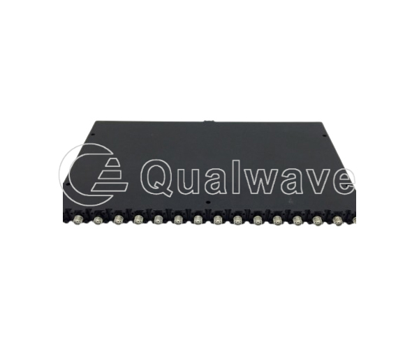
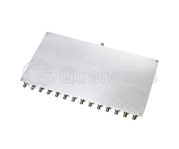
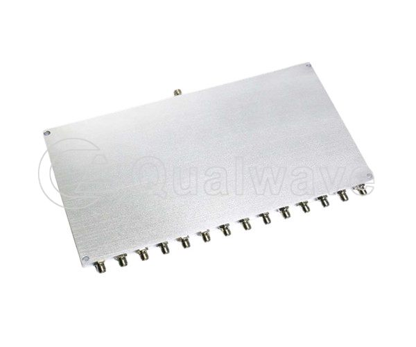
The 14-Way power divider/combiner is a passive RF/microwave component that allows a single input signal to be divided into fourteen equal output signals or combined into one output signal.
1. The input signal can be divided into fourteen outputs to maintain equal output signal power;
2. Fourteen input signals can be combined into one output, keeping the sum of output signal power equal to the input signal power;
3. It has small insertion loss and reflection loss;
4. The 14-way broadband power divider/combiner can work in multiple frequency bands, such as S band, C band and X band.
1. RF transmission system: The 14-way RF power divider/combiner can be used to synthesize input low-power and frequency RF signals into high-power RF signals. It assigns input signals to multiple power amplifier units, each responsible for amplifying a frequency band or signal source, and then merging them into one output port. This method can expand the signal coverage range and provide higher output power.
2. Communication base station: In wireless communication base stations, 14-way microwave power divider/combiner can be used to allocate input RF signals to different power amplifier (PA) units to achieve multi antenna transmission or multi input multi output (MIMO) systems. The power divider can adjust the power distribution between different PA units as needed to optimize power amplification and transmission efficiency.
3. Radar system: In a radar system, a 14-way millimeter wave power divider/combiner is used to distribute the input RF signal to different radar antennas or transmitter units. The power divider can achieve precise control of the phase and power between different antennas or units, thereby forming specific beam shapes and directions. This ability is crucial for radar target detection, tracking, and imaging.
Qualwave supplies 14-way high power dividers/combiners at frequencies from DC to 1.6GHz, with a maximum insertion loss of 18.5dB, a minimum isolation of 18dB, and a maximum standing wave of 1.5.

Part Number |
RF Frequency(GHz, Min.)  |
RF Frequency(GHz, Max.) |
Power as Divider(W) |
Power as Combiner(W) |
Insertion Loss(dB, Max.) |
Isolation(dB, Min.) |
Amplitude Balance(±dB,Max.) |
Phase Balance(±°,Max.) |
VSWR(Max.) |
Connectors |
Lead Time(Weeks) |
|---|---|---|---|---|---|---|---|---|---|---|---|
| QPD14C-500-1600-S | 0.5 | 1.6 | - | - | 18.5 | 18 | ±1.5 | ±3 | 1.5 | SMA | 2~3 |