
Features:
- Broadband
- Small Size
 +86-28-6115-4929
  sales@qualwave.com


Simultaneously allowing high-speed and ultra wideband signals to pass through with minimal signal attenuation. Some biasing devices can transmit the modulated AISG signals together through external LOC modulation and demodulation to achieve control.
1. stability: Bias Tee can maintain the stability of the working point under different temperatures, voltages, and other environments;
2. Linearity: Microwave Bias Tee able to maintain the linear relationship of the output signal under different input signals;
3. Power consumption: Able to reduce power consumption as much as possible while ensuring performance.
Millimeter Wave Bias Tees are widely used in various electronic devices. For example, in audio signal processing, some circuits need specific bias voltage to ensure signal flow; In wireless communication, mm wave Bias Tees are usually used in modem circuits; In amplifier circuits, a biaser is used to bias the signal amplification region to an effective fidelity amplification range, avoiding signal distortion and improving stability.
First, we introduce the standard version.
The frequency range is 50KHz~40GHz.
The maximum RF power is 25W.
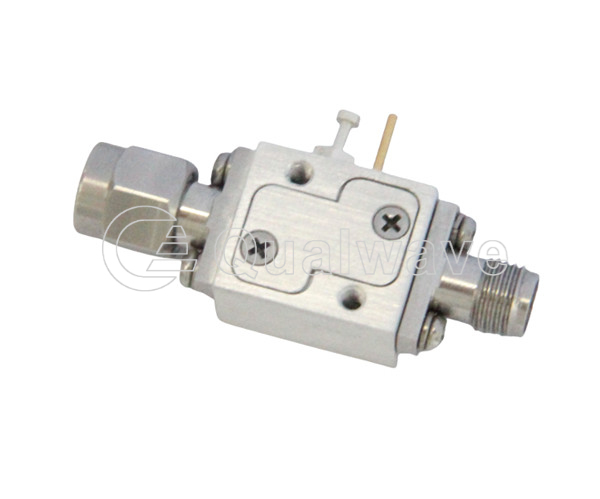
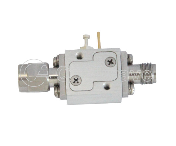
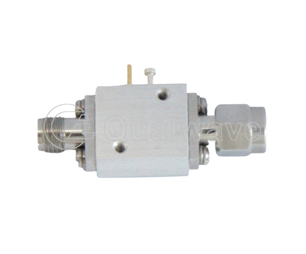
The connectors include four types: SMA, PIN, 2.92mm, N, etc.
The differential loss range is from 0.7 to 3dB.
The voltage range is 0-50V, and there are also options such as 72V and 100V.
The performance of the high RF power version is also excellent.
The frequency range is 5MHz to 40GHz.
The maximum RF power is 150w.
The connectors include SMA and 2.92mm.
The differential loss range is from 0.5 to 1.2ddB.
The voltage range is 0-60V.
Welcome customers to communicate with us about your product needs.

| Standard Bias Tee | ||||||||
|---|---|---|---|---|---|---|---|---|
| Part Number | Frequency (GHz) | RF Power (W max.) | Insertion Loss (dB max.) | VSWR (max.) | Voltage (V) | Current (A) | Conenector | Lead Time (weeks) |
| QBT-30K-26500 | 30K~26.5 | - | 3 | 2.2 | 50 | 0.7 | SMA | 1~4 |
| QBT-50K-18000 | 50K~18 | 10 | 2 | 1.8 | 25 | 0.5 | SMA, PIN | 1~4 |
| QBT-50K-40000 | 50K~40 | 10 | 3 | 2 | 25 | 0.5 | 2.92mm, PIN | 1~4 |
| QBT-0.1-6000 | 100K~6 | 1 | 1.5 | 1.5 | 0~50 | 1 | SMA, PIN | 1~4 |
| QBT-0.5-2000 | 500K~2 | - | 2 | 1.45 | 50 | 6.5 | N | 1~4 |
| QBT-10-4200-N | 0.01~4.2 | 5 | 0.8 | 1.25 | 72 | 2.5 | N | 1~4 |
| QBT-10-5200-S | 0.01~5.2 | 5 | 0.8 | 1.25 | 72 | 2.5 | SMA | 1~4 |
| QBT-10-40000 | 0.01~40 | 10 | 2.2 | 2 | 25 | 0.5 | 2.92mm, PIN | 1~4 |
| QBT-10-50000 | 0.01~50 | 2(min.) | 3 | 2 | 40 | 0.5 | 2.4mm, SMB | 1~4 |
| QBT-100-6000-S | 0.1~6 | 1 | 1.5 | 1.5 | 50 | 0.5 | SMA | 1~4 |
| QBT-100-18000-S | 0.1~18 | 10 | 1.8(typ.) | 1.6(typ.) | 50 | 0.7 | SMA | 1~4 |
| QBT-100-26500-S | 0.1~26.5 | 10 | 2(typ.) | 1.8(typ.) | 50 | 0.7 | SMA | 1~4 |
| QBT-200-12000-S | 0.2~12 | 10 | 0.6 | 1.8 | 0~36 | 0.14@36V | SMA | 1~4 |
| QBT-1000-44000 | 1~44 | 20 | 5 | 1.8(typ.) | 16 | 2 | 2.92mm, SMA | 1~4 |
| QBT-18000-40000 | 18~40 | - | 2 | 2 | 10 | 0.3 | 2.92mm | 1~4 |
| QBT-24900-25100 | 24.9~25.1 | 1 | 0.8 | 2 | 9~30 | 0.03@30V, 0.11@9V | 2.92mm | 1~4 |
| High RF Power Bias Tee | ||||||||
| Part Number | Frequency (GHz) | RF Power (W max.) | Insertion Loss (dB max.) | VSWR (max.) | Voltage (V) | Current (A) | Conenector | Lead Time (weeks) |
| QBTP-5-700-S | 0.005~0.7 | 150 | 0.5 | 1.8 | 0~48 | 3.13@48V | SMA | 1~4 |
| QBTP-10-8000 | 0.01~8 | 100 | 1.5(typ.) | 1.5(typ.) | 100 | 2.5 | SMA, N, PIN | 1~4 |
| QBTP-10-12000 | 0.01~12 | 100 | 2(typ.) | 1.5(typ.) | 100 | 2.5 | SMA, N, PIN | 1~4 |
| QBTP-100-8000-S | 0.1~8 | 50 | 0.6 | 1.3 | 0~40 | 1.25 | SMA | 1~4 |
| QBTP-9000-11000-S | 9~11 | 50 | 0.5 | 2 | 28 | 2 | SMA | 1~4 |
| QBTP-18000-40000-K | 18~40 | 30 | 1.2 | 2 | 50 | 1 | 2.92mm | 1~4 |
| QBTP-18000-40000-K-1 | 18~40 | 60 | 1.2 | 2 | 60 | 1 | 2.92mm, SMA | 1~4 |
| Cryogenic Bias Tee | ||||||||
| Part Number | Frequency (GHz) | RF Power (W max.) | Insertion Loss (dB max.) | VSWR (max.) | Voltage (V) | Current (A) | Conenector | Lead Time (weeks) |
| QCBT-100-1000 | 0.1~1 | - | 0.15 | - | - | - | SMA | 1~4 |