Features:
- Low VSWR
- High Power
- Broadband
 +86-28-6115-4929
  sales@qualwave.com


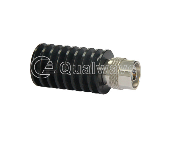
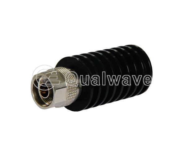
RF coax load is an important component in electronic circuits, usually used to connect to the end of coaxial cables, to absorb the energy of radio frequency (RF) or microwave signals and convert them into thermal energy. Radio Frequency Coaxial terminations are widely used in high-frequency applications such as radio communication, satellite communication, radar, and microwave communication.
1.The impedance of coax loads is usually 50 ohms, which matches the impedance of coaxial cables to minimize signal reflection and loss.
2.It can handle high-power RF and microwave signals, suitable for use in electronic devices and communication systems that require high power.
3.Radio frequency coaxial loads are usually manufactured through precise processes, with high accuracy and stability.
4.High frequency coax loads typically have a wide bandwidth and can cover multiple frequency ranges. This means that it can be used to process signals of various frequencies.
5.Suitable for applications with limited volume, such as micro circuits in microwave integrated circuits and satellite communication systems.
1.Protect the transmitter, ensure the stability and maximum power output of the output circuit and signal, and protect the equipment from damage.
2.Test equipment can be used as a test load to simulate infinite impedance and test the response and performance of the circuit.
3.Adjust the signal, used in attenuators and regulators for microwave signals.
4. Protect the circuit. In some cases, when there are useless signals or noise in the circuit, it can be used to absorb and eliminate these signals or noise.
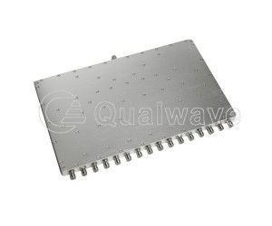
Qualwave supplies broadband and high power coaxial terminations cover the frequency range DC~110GHz. The average power handling is up to 10000 watts. The high frequency coaxial terminations are widely used in many applications.
Welcome new and old customers to call, we will provide more information

Part Number |
Frequency(GHz, Min.)  |
Frequency(GHz, Max.) |
Power(W) |
VSWR(Max.) |
Connectors |
Lead Time(Weeks) |
|---|---|---|---|---|---|---|
| QCT11001 | DC | 110 | 1 | 1.6 | 1.0mm | 0~4 |
| QCT9001 | DC | 90 | 1 | 1.5 | 1.35mm | 0~4 |
| QCT67R5 | DC | 67 | 0.5 | 1.9 | 1.85mm, MMPX | 0~4 |
| QCT6702 | DC | 67 | 2 | 1.3 | 1.85mm | 0~4 |
| QCT6705 | DC | 67 | 5 | 1.35 | 1.85mm | 0~4 |
| QCT6710 | DC | 67 | 10 | 1.4 | 1.85mm | 0~4 |
| QCT50R5 | DC | 50 | 0.5 | 1.4 | 2.4mm | 0~4 |
| QCT5002 | DC | 50 | 2 | 1.25 | 2.4mm | 0~4 |
| QCT5005 | DC | 50 | 5 | 1.3 | 2.4mm | 0~4 |
| QCT5010 | DC | 50 | 10 | 1.4 | 2.4mm | 0~4 |
| QCT5020 | DC | 50 | 20 | 1.4 | 2.4mm | 0~4 |
| QCT40R5 | DC | 40 | 0.5 | 1.5 | 2.92mm, SSMA, SMP, SSMP | 0~4 |
| QCT4002 | DC | 40 | 2 | 1.5 | 2.92mm, SSMA, SMP, SSMP | 0~4 |
| QCT4005 | DC | 40 | 5 | 1.25 | 2.92mm | 0~4 |
| QCT4010 | DC | 40 | 10 | 1.25 | 2.92mm | 0~4 |
| QCT4020 | DC | 40 | 20 | 1.3 | 2.92mm | 0~4 |
| QCT4030 | DC | 40 | 30 | 1.3 | 2.92mm | 0~4 |
| QCT4050 | DC | 40 | 50 | 1.35 | 2.92mm | 0~4 |
| QCT40K1 | DC | 40 | 100 | 1.4 | 2.92mm | 0~4 |
| QCT33R5 | DC | 33 | 0.5 | 1.25 | 3.5mm | 0~4 |
| QCT3302 | DC | 33 | 2 | 1.15 | 3.5mm | 0~4 |
| QCT2602 | DC | 26.5 | 2 | 1.3 | SMA | 0~4 |
| QCT2605 | DC | 26.5 | 5 | 1.25 | 3.5mm, SMA | 0~4 |
| QCT2610 | DC | 26.5 | 10 | 1.25 | 3.5mm, SMA | 0~4 |
| QCT2620 | DC | 26.5 | 20 | 1.3 | SMA | 0~4 |
| QCT2630 | DC | 26.5 | 30 | 1.3 | SMA | 0~4 |
| QCT2650 | DC | 26.5 | 50 | 1.3 | 3.5mm, SMA | 0~4 |
| QCT26K1 | DC | 26.5 | 100 | 1.4 | SMA | 0~4 |
| QCT1801 | DC | 18 | 1 | 1.3 | SMA, SSMA, Quick SMA | 0~4 |
| QCT1802 | DC | 18 | 2 | 1.4 | N, TNC, SSMA, BNC, MMPX | 0~4 |
| QCT1805 | DC | 18 | 5 | 1.4 | N, SMA | 0~4 |
| QCT1807 | DC | 18 | 7 | 1.5 | SMP | 0~4 |
| QCT1810 | DC | 18 | 10 | 1.5 | N, SMA,SMP,TNC | 0~4 |
| QCT1820 | DC | 18 | 20 | 1.4 | N, SMA, 4.3-10 | 0~4 |
| QCT1825 | DC | 18 | 25 | 1.4 | N, SMA, TNC | 0~4 |
| QCT1830 | DC | 12.4 | 30 | 1.25 | N, SMA, 4.3-10 | 0~4 |
| QCT1850 | DC | 18 | 50 | 1.4 | N, SMA, TNC, BNC, 4.3-10 | 0~4 |
| QCT18K1 | DC | 18 | 100 | 1.35 | N, SMA | 0~4 |
| QCT18K15 | DC | 18 | 150 | 1.45 | N | 0~4 |
| QCT18K2 | DC | 18 | 200 | 1.4 | N | 0~4 |
| QCT18K25 | DC | 18 | 250 | 1.45 | N | 0~4 |
| QCT18K3 | DC | 18 | 300 | 1.45 | N | 0~4 |
| QCT18K4 | DC | 18 | 400 | 1.45 | N | 0~4 |
| QCT18K5 | DC | 18 | 500 | 1.6 | N, 7/16 DIN(L29) | 0~4 |
| QCT18K6 | DC | 18 | 600 | 1.45 | N | 0~4 |
| QCT1202 | DC | 12.4 | 2 | 1.25 | Reversed Polarity SMA Male | 0~4 |
| QCT0805 | DC | 8 | 5 | 1.2 | Quick N | 0~4 |
| QCT08K8 | DC | 8 | 800 | 1.45 | N, 7/16 DIN(L29) | 0~4 |
| QCT081K | DC | 8 | 1000 | 1.55 | N | 0~4 |
| Q3 | DC | 6 | 2 | 1.25 | MCX, MMCX | 0~4 |
| QCT0605 | DC | 6 | 5 | 1.15 | QSMA Male | 0~4 |
| QCT0610 | DC | 6 | 10 | 1.2 | QSMA Male | 0~4 |
| QCT063KF | DC | 6 | 3000 | 1.45 | 7/16 DIN(L29) Female | 0~4 |
| QCT0402 | DC | 4 | 2 | 1.25 | SMB, MCX | 0~4 |
| QCT04K8 | DC | 4 | 800 | 1.5 | N, 7/16 DIN(L29) | 0~4 |
| QCT04K8F | DC | 4 | 800 | 1.5 | N, 7/16 DIN(L29) | 0~4 |
| QCT041K | DC | 4 | 1000 | 1.5 | N, 7/16 DIN(L29) | 0~4 |
| QCT041K5 | DC | 4 | 1500 | 1.8 | N, 7/16 DIN(L29) | 0~4 |
| QCT042K | DC | 4 | 2000 | 1.8 | N, 7/16 DIN(L29) | 0~4 |
| QCT033K | DC | 3 | 3000 | 1.4 | IF40, 7/16 DIN(L29) | 0~4 |
| QCT015K | DC | 1 | 5000 | 1.45 | L36, L52, 1-5/8″ (IF70), 7/16 DIN(L29) Female | 0~4 |
| QCT0110K | DC | 1 | 10000 | 1.45 | L36, L52, 1-5/8″ (IF70), 7/16 DIN(L29) | 0~4 |