Features:
- Broadband
- High Power
- Low Insertion Loss
 +86-28-6115-4929
  sales@qualwave.com


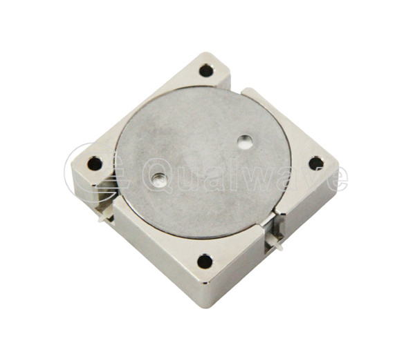
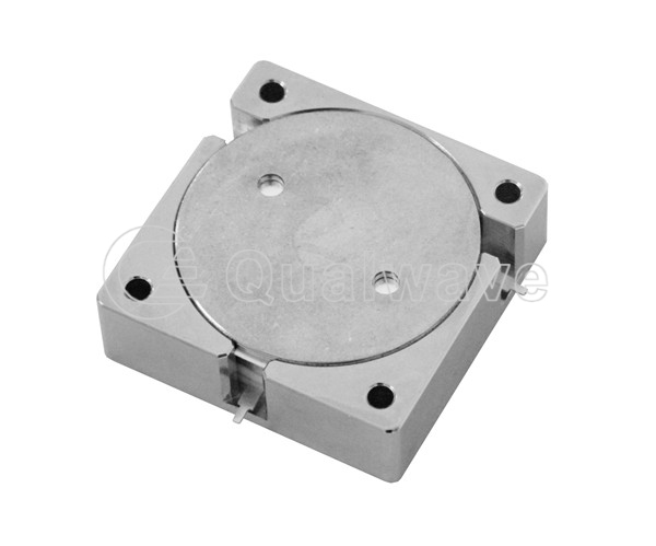
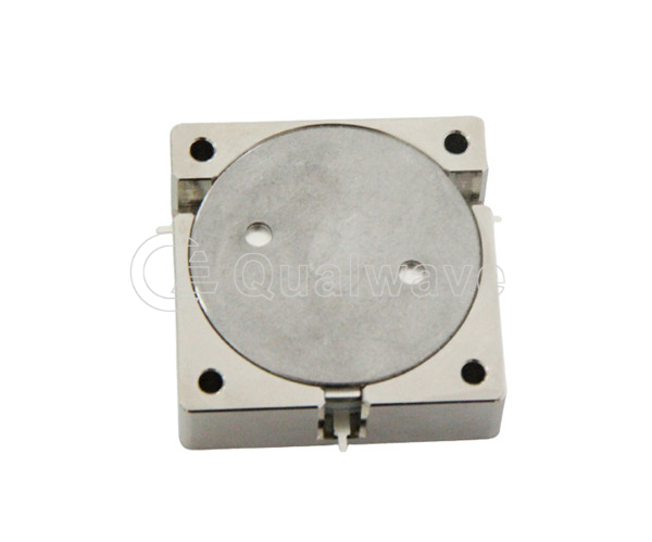
They are designed to be easily mounted on circuit boards and other electronic systems. Drop-in circulators consist of a ferrite circulator, a groundplane, and a housing. The ferrite circulator is a magnetic device that separates the input and output signals based on the direction of their magnetic field. The groundplane provides a uniform ground plane to prevent interference from other components in the system. The housing protects the device from external elements. Drop-in circulators are commonly used in microwave and RF communication systems, including antennas, amplifiers, and transceivers. They help protect sensitive equipment from reflected power, increase isolation between transmitter and receiver, and improve overall system performance. When choosing a drop-in circulator, it is important to consider the frequency range and power handling capability of the device to ensure it will function properly in your specific application.
1. Ultra high reverse isolation: Microwave circulators have a very high degree of reverse isolation, which can isolate signals from one direction to another, ensuring the purity and reliability of the transmitted signal.
2. Low loss: Millimeter wave circulators have very low loss, making them very suitable for applications that require efficient signal transmission.
3. Can withstand high power: This device can withstand high power without worrying about damage caused by power overload.
4. Compact and easy to install: RF circulators are usually more compact than other types of devices, making them easy to install and integrate into the system.
1. Communication: Drop-In circulators are widely used in microwave and wireless communication systems to ensure efficient and high-quality signal transmission.
2. Radar: The radar system requires high reverse isolation, high power resistance, and low loss converters, and Drop-in circulators can meet these requirements.
3. Medical: In medical devices, Octave circulators can help transmit life signals and ensure their high reliability.
4. Antenna system: Broadband circulators can be used as converters in antenna systems to help transmit wireless signals and build high-performance antenna systems.
5. Other application areas: Drop-in circulators are also used in microwave thermal imaging, broadcasting and television, wireless local area networks, and other fields.
Qualwave supplies broadband and high power drop-in circulators in a broad range from 10MHz to 18GHz. The average power is up to 500W. Our drop-in circulators are widely used in many areas.


| Drop-In Circulators | |||||||||||
|---|---|---|---|---|---|---|---|---|---|---|---|
| Part Number | Frequency (GHz) | Bandwidth (MHz, Max.) | IL (dB, max.) | Isolation (dB, Min.) | VSWR (max.) | Average Power (W, Max) | Temperature (℃) | Size (mm) | Lead Time (weeks) | ||
| QDC6060H | 0.02~0.4 | 175 | 2 | 18 | 1.3 | 100 | -10~+60 | 60*60*25.5 | 2~4 | ||
| QDC6466H | 0.02~0.4 | 175 | 2 | 18 | 1.3 | 100 | -10~+60 | 64*66*22 | 2~4 | ||
| QDC5050X | 0.15~0.33 | 70 | 0.7 | 18 | 1.3 | 400 | -30~+75 | 50.8*50.8*14.8 | 2~4 | ||
| QDC4545X | 0.3~1 | 300 | 0.5 | 18 | 1.3 | 400 | -30~+70 | 45*45*13 | 2~4 | ||
| QDC3538X | 0.3~1.85 | 600 | 0.7 | 14 | 1.5 | 300 | -30~+75 | 38*35*11 | 2~4 | ||
| QDC3838X | 0.3~1.85 | 106 | 0.4 | 20 | 1.25 | 300 | -30~+70 | 38*38*11 | 2~4 | ||
| QDC2525X | 0.35~4 | 770 | 0.7 | 15 | 1.45 | 250 | -40~+125 | 25.4*25.4*10 | 2~4 | ||
| QDC2020X | 0.6~4 | 900 | 0.5 | 18 | 1.35 | 100 | -30~+70 | 20*20*8.6 | 2~4 | ||
| QDC1919X | 0.8~4.3 | 900 | 0.5 | 18 | 1.35 | 100 | -30~+70 | 19*19*8.6 | 2~4 | ||
| QDC6466K | 0.95~2 | 1050 | 0.7 | 16 | 1.4 | 100 | -10~+60 | 64*66*26 | 2~4 | ||
| QDC1313T | 1.2~6 | 800 | 0.45 | 18 | 1.3 | 100 | -30~+70 | 12.7*12.7*7.2 | 2~4 | ||
| QDC5050A | 1.5~3 | 1500 | 0.7 | 17 | 1.4 | 100 | 0~+60 | 50.8*49.5*19 | 2~4 | ||
| QDC4040A | 1.7~3 | 1200 | 0.7 | 16 | 1.35 | 200 | 0~+60 | 40*40*20 | 2~4 | ||
| QDC1313M | 1.7~6 | 800 | 0.45 | 18 | 1.3 | 100 | -30~+70 | 12.7*12.7*7.2 | 2~4 | ||
| QDC3234A | 2~4 | 2000 | 0.6 | 16 | 1.35 | 100 | 0~+60 | 32*34*21 | 2~4 | ||
| QDC3030B | 2~6 | 4000 | 1.7 | 12 | 1.6 | 20 | -40~+70 | 30.5*30.5*15 | 2~4 | ||
| QDC1313TB | 2.11~2.17 | 60 | 0.3 | 20 | 1.25 | 50 | -40~+125 | 12.7*12.7*7.2 | 2~4 | ||
| QDC2528C | 2.7~6 | 3500 | 0.8 | 16 | 1.4 | 200 | -30~+70 | 25.4*28*14 | 2~4 | ||
| QDC1822D | 4~5 | 1000 | 0.4 | 18 | 1.35 | 60 | -30~+70 | 18*22*10.4 | 2~4 | ||
| QDC2123B | 4~8 | 4000 | 0.6 | 18 | 1.35 | 60 | 0~+60 | 21*22.5*15 | 2~4 | ||
| QDC1220D | 5~6.5 | 800 | 0.5 | 18 | 1.3 | 60 | -30~+70 | 12*20*9.5 | 2~4 | ||
| QDC1623D | 5~6.5 | 800 | 0.5 | 18 | 1.3 | 50 | -30~+70 | 16*23*9.7 | 2~4 | ||
| QDC1319C | 6~12 | 4000 | 0.5 | 18 | 1.3 | 50 | 0~+60 | 13*19*12.7 | 2~4 | ||
| QDC1620B | 6~18 | 12000 | 1.5 | 10 | 1.9 | 20 | -30~+70 | 16*20.3*14 | 2~4 | ||
| QDC0915D | 7~16 | 6000 | 0.6 | 17 | 1.35 | 30 | -30~+70 | 8.9*15*7.8 | 2~4 | ||
| Dual Junction Drop-In Circulators | |||||||||||
| Part Number | Frequency (GHz) | Bandwidth (MHz, Max.) | IL (dB, max.) | Isolation (dB, Min.) | VSWR (max.) | Average Power (W, Max) | Temperature (℃) | Size (mm) | Lead Time (weeks) | ||
| QDDC7038X | 1.1~1.7 | 600 | 1.2 | 10 | 1.5 | 100 | 0~+60 | 70*38*13 | 2~4 | ||