Features:
- Low VSWR
 +86-28-6115-4929
  sales@qualwave.com


It is generally used as the high-frequency or intermediate frequency preamplifier of various Radio receiver, and the amplification circuit of high-sensitivity electronic detection equipment. A good Low-noise amplifier needs to amplify the signal while producing as low noise and distortion as possible.
1.Impedance matching: The coax impedance matching pad can adjust the impedance between the signal source and the load by changing the parameters of the circuit, such as resistance, capacitance, inductance, etc., to match each other and maximize the transmission of signals.
2.Improve power transmission efficiency: Impedance mismatch will lead to signal reflection and power loss, RF impedance matching pad can reduce signal reflection and power loss, thereby improving power transmission efficiency.
3. Improve signal quality: High frequency impedance matching pad can effectively reduce signal fluctuations and distortion, improve signal quality and stability.
1.Mm wave impedance matching pads be used to adjust the impedance match between the antenna and the transceiver, improve signal transmission efficiency and communication quality.
2.Audio power amplifier: The impedance match is used to adjust the output impedance of the audio power amplifier and match the impedance between the audio power amplifier and the speaker, so that the audio signal can get better amplification effect.
3. Antenna system: Impedance match is used to adjust the input impedance and output impedance of the antenna to improve the transmission and reception efficiency of the antenna. Microwave impedance matching pads have important applications in many electronic devices and systems, which can improve signal transmission efficiency, optimize signal quality, effectively adjust load power, inhibit signal reflection, and make circuits and systems work better.
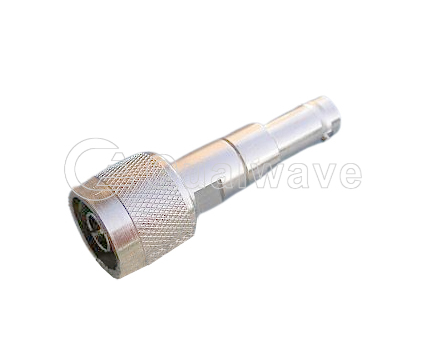
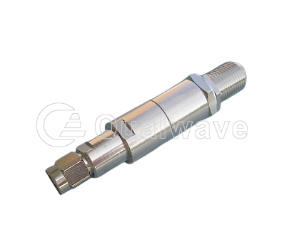
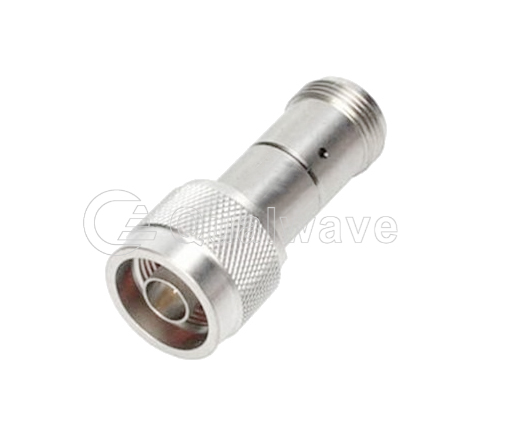
Qualwave Inc. provides radio frequency impedance matching pads with a power range of 2~50W, including SMA, N, BNC and F, which are suitable for wireless, transmitter, radar, laboratory test and other areas.


Part Number |
Frequency(GHz, Min.) |
Frequency(GHz, Max.) |
Power(w) |
Insertion Loss(dB, Max.) |
VSWR(Max.) |
Typical Flatness(dB Max.) |
Impedance |
RF Connector |
Lead Time (weeks) |
|---|---|---|---|---|---|---|---|---|---|
| QIMP1302 | DC | 1.3 | 2 | 5.7 | 1.06 | 0.1 | 50Ω, 75Ω | SMA, N, BNC, F | 2~4 |
| QIMP1305 | DC | 1.3 | 5 | 5.7 | 1.06 | 0.1 | 50Ω, 75Ω | SMA, N, BNC, F | 2~4 |
| QIMP1350 | DC | 1.3 | 50 | 5.7 | 1.2 | 0.1 | 50Ω, 75Ω | SMA, N, BNC, F | 2~4 |
| QIMP3002 | DC | 3 | 2 | 5.7 | 1.15 | 0.15 | 50Ω, 75Ω | SMA, N, BNC, F | 2~4 |
| QIMP3005 | DC | 3 | 5 | 5.7 | 1.15 | 0.15 | 50Ω, 75Ω | SMA, N, BNC, F | 2~4 |
| QIMP3050 | DC | 3 | 50 | 5.7 | 1.25 | 0.15 | 50Ω, 75Ω | SMA, N, BNC, F | 2~4 |