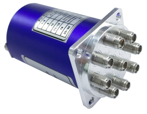
An RF coaxial switch is a device used in RF and microwave communication systems to establish or switch connections between different coaxial cable paths. It allows for the selection of a specific input or output path from multiple options, depending on the desired configuration.
The following characteristics:
1. Quick switching: RF coaxial switches can quickly switch between different RF signal paths, and the switching time is generally at the millisecond level.
2. Low insertion loss: The switch structure is compact, with low signal loss, which can ensure the transmission of signal quality.
3. High isolation: The switch has high isolation, which can effectively reduce mutual interference between signals.
4. High reliability: The RF coaxial switch adopts high-quality materials and high-precision manufacturing technology, which has high reliability and stability.

Qualwaves Inc. supplies RF coaxial switches with a working frequency range of DC~110GHz and a lifespan of up to 2 million cycles.
This article introduces 2.92mm coaxial switches for DC~40GHz and SP7T~SP8T.
1.Electrical Characteristics
Frequency: DC~40GHz
Impedance: 50Ω
Power: Please refer to the following power curve chart
(Based on an ambient temperature of 20°C)
QMS8K series
Frequency Rang (GHz) |
Insertion Loss (dB) |
Isolation (dB) |
VSWR |
DC~12 |
0.5 |
70 |
1.4 |
12~18 |
0.6 |
60 |
1.5 |
18~26.5 |
0.8 |
55 |
1.7 |
26.5~40 |
1.1 |
50 |
2.0 |
Voltage and current
Voltage (V) |
+12 |
+24 |
+28 |
Current (mA) |
300 |
150 |
140 |
2.Mechanical Properties
Size *1 :41*41*53mm
1.614*1.614*2.087in
Switching Sequence: Break before Make
Switching Time: 15mS max.
Operation Life: 2M Cycles
Vibration (operating): 20-2000Hz, 10G RMS
Mechanical Shock (non-operating): 30G, 1/2sine, 11mS
RF Connectors: 2.92mm Female
Power Supply & Control Interface Connectors: D-Sub 15 Male/D-Sub 26 Male
Mounting: 4-Φ4.1mm through-hole
[1] Excludeconnectors.
3.Environment
Temperature: -25~65℃
Extended temperature: -45~+85℃
4.Outline Drawings

Unit: mm [in]
Tolerance: ±0.5mm [±0.02in]
5.Pin Numbering
Normally Open
| Pin | Function | Pin | Function |
| 1~8 | V1~V8 | 18 | Indicator (COM) |
| 9 | COM | 19 | VDC |
| 10~17 | Indicator (1~8) | 20~26 | NC |
Normally Open & TTL
| Pin | Function | Pin | Function |
| 1~8 | A1~A8 | 11~18 | Indicator (1~8) |
| 9 | VDC | 19 | Indicator (COM) |
| 10 | COM | 20~25 | NC |
6.Driving Schematic Diagram

7.How To Order
QMSVK-F-WXYZ
V: 7~8 (SP7T~SP8T)
F: Frequency in GHz
W: Actuator Type. Normally Open: 3.
X: Voltage. +12V: E, +24V: K, +28V: M.
Y: Power Interface. D-Sub: 1.
Z: Additional Options.
Additional Options
TTL: T
Indicators: I Extended
Temperature: Z
Positive Common
Waterproof Sealing Type
Examples:
To order a SP8T switch, DC~40GHz, Normally Open, +12V, D-Sub, TTL,
Indicators, specify QMS8K-40-3E1TI.
Customization is available upon request.
If you have any questions, please feel free to call for consultation.
Post time: Dec-06-2024
 +86-28-6115-4929


