Features:
- Durable
- Low Insertion
- Loss Low VSWR
 +86-28-6115-4929
  sales@qualwave.com


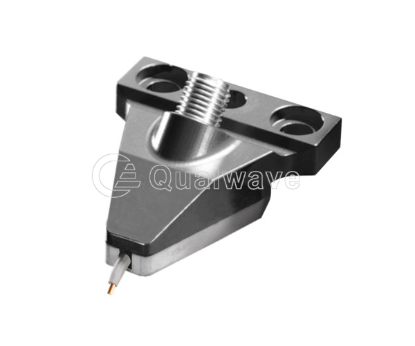
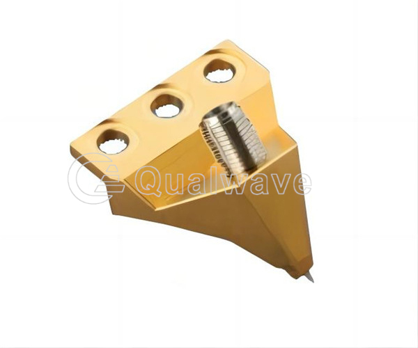
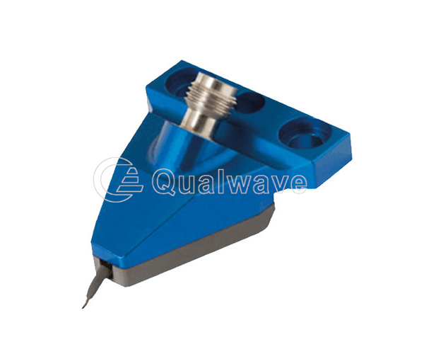
Microwave probes are electronic devices used for measuring or testing electrical signals or properties in electronic circuits. They are usually connected to an oscilloscope, multimeter, or other test equipment to collect data about the circuit or component being measured.
1.Durable Microwave probe
2.Available in four distances of 100/150/200/25 microns
3.DC to 67 GHz
4.Insertion loss less than 1.4 dB
5.VSWR less than 1.45dB
6.Beryllium copper material
7.High current version available (4A)
8.Light indentation and reliable performance
9.Anti oxidation nickel alloy probe tip
10.Custom configurations available
11.Suitable for on chip testing, junction parameter extraction, MEMS product testing, and on chip antenna testing of microwave integrated circuits
1. Excellent measurement accuracy and repeatability
2. Minimal damage caused by short scratches on aluminum pads
3. Typical contact resistance<0.03Ω
1. RF circuit test:
Millimeter wave probes can be connected to the test point of the RF circuit, by measuring the amplitude, phase, frequency and other parameters of the signal to evaluate the performance and stability of the circuit. It can be used to test RF power amplifier, filter, mixer, amplifier and other RF circuits.
2. Wireless communication system test:
Radio frequency probe can be used to test wireless communication devices, such as mobile phones, Wi-Fi routers, Bluetooth devices, etc. By connecting the mm-wave probe to the antenna port of the device, parameters such as transmit power, receive sensitivity, and frequency deviation can be measured to evaluate the performance of the device and guide system debugging and optimization.
3. RF antenna test:
Coaxial probe can be used to measure the radiation characteristics of the antenna and input impedance. By touching the RF probe to the antenna structure, the antenna's VSWR (voltage standing wave ratio), radiation mode, gain and other parameters can be measured to evaluate the performance of the antenna and carry out antenna design and optimization.
4. RF signal monitoring:
RF probe can be used to monitor the transmission of RF signals in the system. It can be used to detect signal attenuation, interference, reflection and other problems, help find and diagnose faults in the system, and guide the corresponding maintenance and debugging work.
5. Electromagnetic compatibility (EMC) test:
High frequency probes can be used to perform EMC tests to assess the sensitivity of electronic devices to RF interference in the surrounding environment. By placing an RF probe near the device, it is possible to measure the device's response to external RF fields and evaluate its EMC performance.
Qualwave Inc. provides DC~110GHz high frequency probes, which have the characteristics of long service life, low VSWR and low insertion loss, and are suitable for microwave test and other areas.

| Single Port Probes | ||||||||||
|---|---|---|---|---|---|---|---|---|---|---|
| Part Number | Frequency (GHz) | Pitch (μm) | Tip Size (m) | IL (dB Max.) | VSWR (Max.) | Configuration | Mounting Styles | Connector | Power (W Max.) | Lead Time (weeks) |
| QSP-26 | DC~26 | 200 | 30 | 0.6 | 1.45 | SG | 45° | 2.92mm | - | 2~8 |
| QSP-26.5 | DC~26.5 | 150 | 30 | 0.7 | 1.2 | GSG | 45° | SMA | - | 2~8 |
| QSP-40 | DC~40 | 100/125/150/250/300/400 | 30 | 1 | 1.6 | GS/SG/GSG | 45° | 2.92mm | - | 2~8 |
| QSP-50 | DC~50 | 150 | 30 | 0.8 | 1.4 | GSG | 45° | 2.4mm | - | 2~8 |
| QSP-67 | DC~67 | 100/125/150/240/250 | 30 | 1.5 | 1.7 | GS/SG/GSG | 45° | 1.85mm | - | 2~8 |
| QSP-110 | DC~110 | 50/75/100/125/150 | 30 | 1.5 | 2 | GS/GSG | 45° | 1.0mm | - | 2~8 |
| Dual Port Probes | ||||||||||
| Part Number | Frequency (GHz) | Pitch (μm) | Tip Size (m) | IL (dB Max.) | VSWR (Max.) | Configuration | Mounting Styles | Connector | Power (W Max.) | Lead Time (weeks) |
| QDP-40 | DC~40 | 125/150/650/800/1000 | 30 | 0.65 | 1.6 | SS/GSGSG | 45° | 2.92mm | - | 2~8 |
| QDP-50 | DC~50 | 100/125/150/190 | 30 | 0.75 | 1.45 | GSSG | 45° | 2.4mm | - | 2~8 |
| QDP-67 | DC~67 | 100/125/150/200 | 30 | 1.2 | 1.7 | SS/GSSG/GSGSG | 45° | 1.85mm, 1.0mm | - | 2~8 |
| Manual Probes | ||||||||||
| Part Number | Frequency (GHz) | Pitch (μm) | Tip Size (m) | IL (dB Max.) | VSWR (Max.) | Configuration | Mounting Styles | Connector | Power (W Max.) | Lead Time (weeks) |
| QMP-20 | DC~20 | 700/2300 | - | 0.5 | 2 | SS/GSSG/GSGSG | Cable Mount | 2.92mm | - | 2~8 |
| QMP-40 | DC~40 | 800 | - | 0.5 | 2 | GSG | Cable Mount | 2.92mm | - | 2~8 |
| Differential TDR Probes | ||||||||||
| Part Number | Frequency (GHz) | Pitch (μm) | Tip Size (m) | IL (dB Max.) | VSWR (Max.) | Configuration | Mounting Styles | Connector | Power (W Max.) | Lead Time (weeks) |
| QDTP-40 | DC~40 | 0.5~4 | - | - | - | SS | - | 2.92mm | - | 2~8 |
| Calibration Substrates | ||||||||||
| Part Number | Pitch (μm) | Configuration | Dielectric Constant | Thickness | Outline Dimension | Lead Time (weeks) | ||||
| QCS-75-250-GS-SG-A | 75-250 | GS/SG | 9.9 | 25mil (635μm) | 15*20mm | 2~8 | ||||
| QCS-100-GSSG-A | 100 | GSSG | 9.9 | 25mil (635μm) | 15*20mm | 2~8 | ||||
| QCS-100-250-GSG-A | 100-250 | GSG | 9.9 | 25mil (635μm) | 15*20mm | 2~8 | ||||
| QCS-250-500-GSG-A | 250-500 | GSG | 9.9 | 25mil (635μm) | 15*20mm | 2~8 | ||||
| QCS-250-1250-GSG-A | 250-1250 | GSG | 9.9 | 25mil (635μm) | 15*20mm | 2~8 | ||||