Features:
- Low VSWR
 +86-28-6115-4929
  sales@qualwave.com


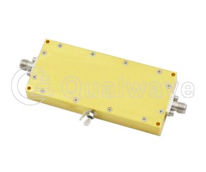
In microwave circuits, the power of signals is often very high. If excessive power cannot be fully controlled, it will easily cause many problems in the circuit, such as exceeding the maximum energy tolerance range of circuit components and causing various deviations. The use of waveguide variable attenuators can effectively meet the demand for reducing signal power and ensure the normal operation of microwave circuits.
The working principle of continuously variable attenuator is based on the propagation characteristics of electromagnetic waves in waveguides. It mainly consists of waveguides, impedance matching devices, and variable conductor blocks. When a signal passes through a waveguide, a portion of the energy is absorbed by the conductor block, thereby reducing the signal power
When the conductor block is a mechanical structure that can be manually adjusted by the user, it is a rotary stepped attenuators. The manually variable attenuators are indispensable helpers in electronic communication systems.
1. To ensure the balance of signal levels in the signal chain, waveguide variable attenuators can be achieved by reducing signal strength.
2. Expanding the dynamic range of the system is also a strong point of the rotary stepped attenuator, which can ensure stable operation of the system.
3. Providing impedance matching can avoid signal reflection and loss, ensuring the stability of signal transmission.
The waveguide variable attenuator is widely used in microwave communication and laboratory testing. It can be used to adjust signal strength to meet different needs. For example, in the laboratory, rotary step can provide flexible adjustment capabilities when signal strength needs to be changed to test equipment performance. In microwave communication, continuously variable attenuators can be used to adjust signal strength to ensure that the signal is not too strong or too weak during transmission.
The advantages of variable attenuators are simplicity, ease of use, and flexible adjustment. By manual operation, users can precisely control the amount of signal attenuation as needed. However, compared to automatic waveguide attenuators, the adjustment range of manual waveguide attenuators may be narrower, and the adjustment process requires a certain amount of time and accuracy.
Qualwave supplies low VSWR and high attenuation flatness from 0.96 to 500GHz. The attenuation range is 0~40dB.

Part Number |
Frequency(GHz, min.)  |
Frequency(GHz, max.) |
Attenuation Range(dB) |
VSWR(max.) |
Waveguide Size |
Flange |
Material |
Lead Time(weeks) |
|---|---|---|---|---|---|---|---|---|
| QWVA-2.2-B-7 | 325 | 500 | 0~40 | 1.4 | WR-2.2 | UG387/U | Brass | 2~6 |
| QWVA-3.4-B-6 | 220 | 325 | 0~30 | 1.3 | WR-3.4 | UG385/U | Brass | 2~6 |
| QWVA-3.4-B-7 | 220 | 325 | 0~40 | 1.4 | WR-3.4 | UG387/U | Brass | 2~6 |
| QWVA-4.3-B-6 | 170 | 260 | 0~30 | 1.3 | WR-4.3 | UG385/U | Brass | 2~6 |
| QWVA-5.1-B-6 | 140 | 220 | 0~30 | 1.3 | WR-5.1 | UG385/U | Brass | 2~6 |
| QWVA-5.1-B-7 | 140 | 220 | 0~40 | 1.4 | WR-5.1 | UG387/U | Brass | 2~6 |
| QWVA-6.5-B-6 | 110 | 170 | 0~30 | 1.2 | WR-6.5 | UG385/U | Brass | 2~6 |
| QWVA-8-B-6 | 90 | 140 | 0~30 | 1.2 | WR-8 | UG385/U | Brass | 2~6 |
| QWVA-10-B-12 | 73.8 | 110 | 0~30 | 1.3 | WR-10 (BJ900) | UG387/UM | Brass | 2~6 |
| QWVA-12-B-7 | 60.5 | 91.5 | 0~30 | 1.4 | WR-12 (BJ740) | UG387/U | Brass | 2~6 |
| QWVA-15-B-6 | 49.8 | 75.8 | 0~30 | 1.3 | WR-15 (BJ620) | UG385/U | Brass | 2~6 |
| QWVA-19-B-10 | 39.2 | 59.6 | 0~30 | 1.25 | WR-19 (BJ500) | UG383/UM | Brass | 2~6 |
| QWVA-22-B-5 | 32.9 | 50.1 | 0~30 | 1.3 | WR-22 (BJ400) | UG-383/U | Brass | 2~6 |
| QWVA-28-B-1 | 26.5 | 40.0 | 0~30 | 1.2 | WR-28 (BJ320) | FBP320 | Brass | 2~6 |
| QWVA-34-B-1 | 21.7 | 33.0 | 0~30 | 1.3 | WR-34 (BJ260) | FBP260 | Brass | 2~6 |
| QWVA-42-B-1 | 17.6 | 26.7 | 0~30 | 1.3 | WR-42 (BJ220) | FBP220 | Brass | 2~6 |
| QWVA-51-B-1 | 14.5 | 22.0 | 0~30 | 1.25 | WR-51 (BJ180) | FBP180 | Brass | 2~6 |
| QWVA-62-B-1 | 11.9 | 18.0 | 0~30 | 1.25 | WR-62 (BJ140) | FBP140 | Brass | 2~6 |
| QWVA-75-B-1 | 9.84 | 15.0 | 0~30 | 1.2 | WR-75 (BJ120) | FBP120 | Brass | 2~6 |
| QWVA-90-A-2 | 10 | 11 | 0~30 | 1.5 | WR-90 (BJ100) | FDP100 | Aluminum | 2~6 |
| QWVA-90-B-1 | 9.2 | 9.8 | 0~30 | 1.35 | WR-90 (BJ100) | FBP100 | Brass | 2~6 |
| QWVA-112-A-2 | 7 | 8 | 0~30 | 1.5 | WR-112 (BJ84) | FDP84 | Aluminum | 2~6 |
| QWVA-112-B-1 | 6.57 | 9.99 | 0~30 | 1.25 | WR-112 (BJ84) | FBP84 | Brass | 2~6 |
| QWVA-112-B-2 | 7 | 10 | 0~30 | 1.2 | WR-112 (BJ84) | FDP84 | Brass | 2~6 |
| QWVA-137-A-2 | 6 | 7 | 0~30 | 1.6 | WR-137 (BJ70) | FDP70 | Aluminum | 2~6 |
| QWVA-137-B-2 | 5.38 | 8.17 | 0~30 | 1.25 | WR-137 (BJ70) | FDP70 | Brass | 2~6 |
| QWVA-159-A-2 | 4.64 | 7.05 | 0~30 | 1.25 | WR-159 (BJ58) | FDP58 | Aluminum | 2~6 |
| QWVA-187-A-2 | 3.94 | 5.99 | 0~30 | 1.25 | WR-187 (BJ48) | FDP48 | Aluminum | 2~6 |
| QWVA-229-A-2 | 3.22 | 4.90 | 0~30 | 1.25 | WR-229 (BJ40) | FDP40 | Aluminum | 2~6 |
| QWVA-284-A-2 | 2.60 | 3.95 | 0~30 | 1.25 | WR-284 (BJ32) | FDP32 | Aluminum | 2~6 |
| QWVA-340-A-2 | 2.17 | 3.3 | 0~30 | 1.25 | WR-340 (BJ26) | FDP26 | Aluminum | 2~6 |
| QWVA-430-A-2 | 1.72 | 2.61 | 0~30 | 1.25 | WR-430 (BJ22) | FDP22 | Aluminum | 2~6 |
| QWVA-510-A-2 | 1.45 | 2.20 | 0~30 | 1.25 | WR-510 (BJ18) | FDP18 | Aluminum | 2~6 |
| QWVA-650-A-2 | 1.13 | 1.73 | 0~30 | 1.25 | WR-650 (BJ14) | FDP14 | Aluminum | 2~6 |
| QWVA-770-A-2 | 0.96 | 1.46 | 0~30 | 1.25 | WR-770 (BJ12) | FDP12 | Aluminum | 2~6 |